5.8. [ Transform ] section
5.8.1. Formats
Coordinate transformation can be defined in this section. The transformation is available in the [source], [surface], and [cell] sections, tallies with r-z and xyz mesh, and definition of magnetic and electro-magnetic fields. Only $ and c (with a following half-width space) can be used as comment marks. Using [transform], only rotation and translation of the coordinate can be set, and enlarge or shrink cannot be set.
Formats are shown below.
[ Transform ]
  TRn  X0 Y0 Z0  B1 B2 B3 B4 B5 B6 B7 B8 B9  M
Here, transform number is specified by n of TRn, \(X_0\), \(Y_0\), and \(Z_0\) are \(X\)-, \(Y\)-, and \(Z\)-components of the translation, respectively, and \(B_i (i=1,\cdots,9)\) are input parameters to define the rotation. The last parameter \(M\) is an option which changes roles of \(B_i\) and equations of the coordinate transformation.
Item |
Explanation |
|---|---|
\(n\) |
Transform number. Use any number from 1 to 999,999. |
\(X_0, Y_0, Z_0\) |
x, y, z components of translation. The unit is cm. |
\(B_1 \sim B_9\) |
Input parameters to define rotation matrix. When \(M=\pm1\), please see (5.8.1) and (5.8.2) in more detail. The determinant of the matrix is automatically adjusted to 1. When \(M=\pm2, \pm3\), please see Section 5.8.2.2 and Section 5.8.2.3. |
\(M\) |
Option for coordinate transformation. When this value is positive, PHITS rotates the object prior to translating it; if negative, PHITS translates the object prior to rotating it. When \(M=\pm1\), components of the rotation matrix should be directly given as \(B_i(i=1,\cdots,9)\). When \(M=\pm2\) or \(\pm3\), only rotations around x-, y-, and z-axes can be treated by using simple input. When \(M=\pm2\), the center of the rotation is the origin, and the order of the rotation is z, y, x. On the other hand, when \(M=\pm3\), a center coordinate of the rotation can be specified, and the order of the rotation can be changed. Rotation angles should be set in the unit of radian in the case of TRn format, while angles in degree should be set in the case of *TRn. However, when \(M=\pm1\), \(\theta_i\) corresponding to Bi = \(\cos(\theta_i)\) is given in degrees. |
5.8.2. Mathematical definition and usage of transformation
When the coordinates before and after the transformation are defined as (x, y, z) and (x’, y’, z’), respectively, the mathematical definition is the following except the case of tallies.
5.8.2.1. The case of \(M=\pm1\)
When \(M=\pm1\), components of a rotation matrix can be directly given by \(B_i(i=1,\cdots,9)\). The coordinates before and after the transformation are defined as (x, y, z) and (x’, y’, z’), respectively. The mathematical definition in the case of \(M=1\) is given as
for \(M=-1\),
The geometrical interpretation of B1-B9 is the cosine of the angles between the x-, y-, and z-axes before and after the transformation (or the angles in degrees if an asterisk (*) is placed before tr). In the case of \(M=1\), PHITS rotates the object prior to translating it. On the other hand, when \(M=-1\), PHITS translates the object prior to rotating it. The rotation is performed at the origin of the xyz coordinate system. Note that the direction of the translation setting \(M=1\) and \(-1\) is opposite each other. For example, if you want to transform a cell in the +x direction by 10 cm, you have to set \(X_0=10\) and \(-10\) in the cases of \(M=1\) and \(-1\), respectively. This rule is also applied to the cases of \(M=\pm2, \pm3\).
     1:  [ Transform ]
     2:  set: c10[90]  $ angle of around Z (degree)
     3:  set: c20[30]  $ angle of around Y (degree)
     4:  set: c30[0]   $ angle of around X (degree)
     5:
     6:  tr1   0 0 0
     7:        cos(c10/180*pi)*cos(c20/180*pi)
     8:        sin(c10/180*pi)*cos(c30/180*pi)+cos(c10/180*pi)*sin(c20/180*pi)*sin(c30/180*pi)
     9:        sin(c10/180*pi)*sin(c30/180*pi)-cos(c10/180*pi)*sin(c20/180*pi)*cos(c30/180*pi)
    10:       -sin(c10/180*pi)*cos(c20/180*pi)
    11:        cos(c10/180*pi)*cos(c30/180*pi)-sin(c10/180*pi)*sin(c20/180*pi)*sin(c30/180*pi)
    12:        cos(c10/180*pi)*sin(c30/180*pi)+sin(c10/180*pi)*sin(c20/180*pi)*cos(c30/180*pi)
    13:        sin(c20/180*pi)
    14:       -cos(c20/180*pi)*sin(c30/180*pi)
    15:        cos(c20/180*pi)*cos(c30/180*pi)
    16:        1
In this example, tr1 rotates the coordinate by c10 degrees around the z-axis, c20 degrees around the y-axis and finally c30 degrees around the x-axis. By setting c10, c20, and c30, the rotation can be defined.
5.8.2.2. The case of \(M=\pm2\)
When \(M=\pm2\), only rotations around x-, y-, and z-axes can be treated by using simple input. Input of only rotation angles is enough, and that of all components of a rotation matrix is not needed. Note that you cannot change the order of the rotation, z, y, x.
Formats are shown below.
TRn X0 Y0 Z0 theta_z theta_y theta_x 0 0 0 0 0 0 2
\(X_0\), \(Y_0\), and \(Z_0\) are x, y, and z components of translation, respectively. \(\theta_z\), \(\theta_y\), and \(\theta_x\) are rotation angles around z-, y-, x-axes, respectively. For \(B_4\)-\(B_9\), any values, such as zero, should be set.
The direction of the rotation around each axis is shown in Fig. 5.8.1. Each rotation matrix is gives as
By using these matrixes, the mathematical definition in the case of \(M=2\) is given as
for \(M=-2\),
Here, the coordinates before and after the transformation are (x, y, z) and (x’, y’, z’), respectively. Note that the direction of the translation setting \(M=2\) and \(-2\) is opposite each other.
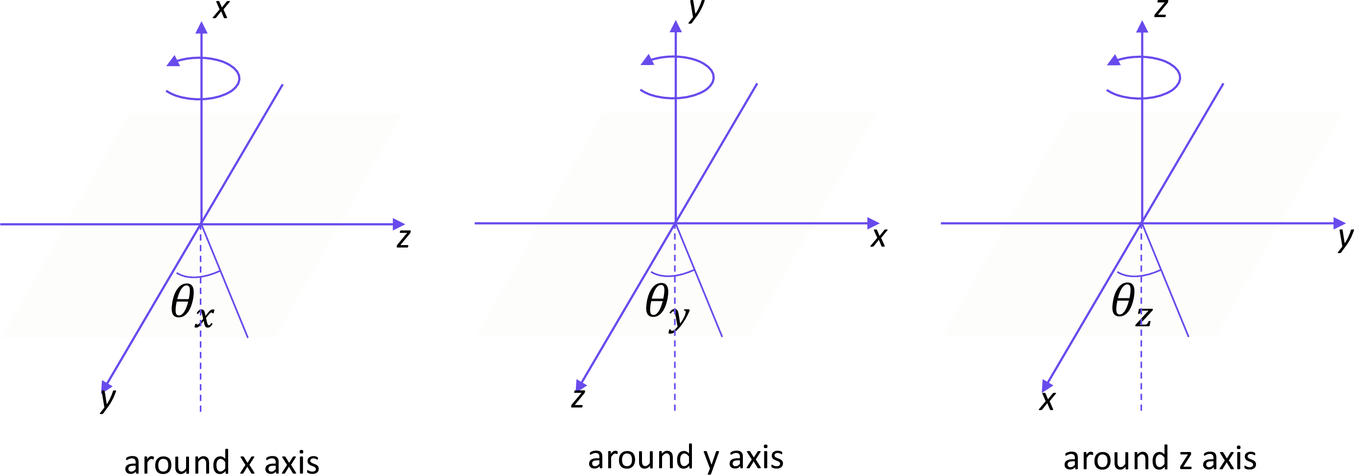
Fig. 5.8.1 Direction of rotation around the x-, y-, and z-axes.
     1:   [ Transform ]
     2:   *tr1   0 0 0  90   30   0  0 0 0 0 0 0  2
     3:   tr2    0 0 0  pi/2 pi/6 0  0 0 0 0 0 0  2
This is an example of \(M=2\), which gives the same definition of the rotation as Listing 5.8.1. The rotation angles of *TR1 are given in units of degree, and those of TR2 are given in radian.
5.8.2.3. The case of \(M=\pm3\)
By using this option, you can change a center coordinate of rotations and the order of rotation axes.
Formats are shown below.
TRn X0 Y0 Z0 XC YC ZC A1 theta_1 A2 theta_2 A3 theta_3 3
Here, \(X_0\), \(Y_0\), and \(Z_0\) are x, y, and z components of translation, respectively, and \(X_C\), \(Y_C\), and \(Z_C\) are x, y, and z components of the center coordinates for the rotation. \(A_i\) and \(\theta_i (i=1,2,3)\) are, respectively, rotation axis and angle of the \(i\)-th rotation. \(A_i=1,2,3\) mean, respectively, a rotation around the x-, y-, and z-axes as the \(i\)-th rotation. On the other hand, \(A_i=0\) indicates that rotation is not necessary anymore. For example, if you want to rotate only around the y-axis, you have to set \(A_1=2\), and \(A_2=A_3=0\).
The coordinates before and after the transformation are defined as (x, y, z) and (x’, y’, z’), respectively. The mathematical definition in the case of \(M=3\) is given as
When \(M=-3\),
Note that the direction of the translation setting \(M=3\) and \(-3\) is opposite each other.
     1:   [ Transform ]
     2:   *tr1  0.0 0.0 5.0   0.0 10.0 0.0   2 45.0   3 -60.0   0 0.0   3
This is an example of \(M=3\). PHITS rotates the object at the center of (0, 10, 0) around the y-axis by 45 deg and the z-axis by \(-60\) deg, and then translates along the +z-axis by 5 cm.
5.8.3. The case of tally
The transformed tally displays the result in the coordinate system after the transformation, so-called body-fixed coordinate system. In this case, because the tally result is output in the coordinate system after the transformation, the relation between (x, y, z) and (x’, y’, z’) in the equations in the case of tally is opposite to that in the other case. For example, when \(M=1\), the coordinates after the transformation (x’, y’, z’), which are tally coordinates, can be given as
Here, the coordinates before the transformation are (x, y, z). For example, an object at x=20 cm in the original tally coordinate system is shifted to the position at x’=20-X_0 cm in the transformed tally. When \(X_0\) is positive, the object is shifted by \(-X_0\) along the x-axis. On the other hand, when \(M=-1\), the definition is given as
The change in the cases of \(M=\pm2, \pm3\) is the same as that in \(M=\pm1\).