5.5. [ Surface ] section
5.5.1. Formats
In the [surface] section, surfaces can be set to define cells in the [cell] section. Several surfaces, including planes, sphere surfaces, cylinder surfaces, and others, can be set in terms of the parameters in the equations defining their respective shapes. Only $ and c followed by a half-width space can be used as comment marks in [surface]. To use continuation lines, place at least five blanks at the line head instead of using the line sequential mark at the end of the line.
The [surface] section is defined in the order: surface number, coordinate transform number, surface symbol, and surface definition. These are explained in Table 5.5.1. The format is as follows.
[ Surface ]
  surface number    transform number    surface symbol    surface definition
The surfaces expressed by the equations in Table 5.5.2 or the macro body in Table 5.5.3 can be referred to using their surface symbols. In addition, mathematical expressions and user-defined variables can be used for surface definition. Reflective and white boundary conditions can be set by writing * and +, respectively, before the surface number. For example, *10 indicates that surface 10 is a reflective boundary. The reflective boundary condition is useful to develop an infinite repeated structure. However, the function of the reflective boundary does not work in tetra-mesh geometry. Instead, by preparing a physically meaningless thin region in the tetra-mesh geometry and defining reflection boundary inside, the reflection boundary in tetra-mesh geometry can be realized.
item |
explanation |
|---|---|
surface number |
Use any number from 1 to 999,999. |
transform number |
Specify the number n of TRn defined in the [transform] section. Do not specify it if coordinate transform is not used. |
surface symbol |
Specify a surface symbol in Table 5.5.2 and Table 5.5.3. |
surface definition |
Specify 1 to 15 input parameters depending on the surface symbol. |
Surface symbol |
Type |
Explanation |
Equation |
Parameters |
|---|---|---|---|---|
P |
plane |
multi-purpose |
\(Ax+By+Cz-D=0\) |
\(A, B, C, D\) |
PX |
plane |
vertical with X-axis |
\(x-D=0\) |
\(D\) |
PY |
plane |
vertical with Y-axis |
\(y-D=0\) |
\(D\) |
PZ |
plane |
vertical with Z-axis |
\(z-D=0\) |
\(D\) |
P |
plane |
defined by 3 coordinates |
\(x_1,y_1,z_1,\ x_2,y_2,z_2,\ x_3,y_3,z_3\) |
|
SO |
sphere |
origin is center |
\(x^2+y^2+z^2-R^2=0\) |
\(R\) |
S |
sphere |
multi-purpose |
\((x-x_0)^2+(y-y_0)^2+(z-z_0)^2-R^2=0\) |
\(x_0, y_0, z_0, R\) |
SX |
sphere |
center on X-axis |
\((x-x_0)^2+y^2+z^2-R^2=0\) |
\(x_0, R\) |
SY |
sphere |
center on Y-axis |
\(x^2+(y-y_0)^2+z^2-R^2=0\) |
\(y_0, R\) |
SZ |
sphere |
center on Z-axis |
\(x^2+y^2+(z-z_0)^2-R^2=0\) |
\(z_0, R\) |
C/X |
cylinder |
parallel with X-axis |
\((y-y_0)^2+(z-z_0)^2-R^2=0\) |
\(y_0, z_0, R\) |
C/Y |
cylinder |
parallel with Y-axis |
\((x-x_0)^2+(z-z_0)^2-R^2=0\) |
\(x_0, z_0, R\) |
C/Z |
cylinder |
parallel with Z-axis |
\((x-x_0)^2+(y-y_0)^2-R^2=0\) |
\(x_0, y_0, R\) |
CX |
cylinder |
on X-axis |
\(y^2+z^2-R^2=0\) |
\(R\) |
CY |
cylinder |
on Y-axis |
\(x^2+z^2-R^2=0\) |
\(R\) |
CZ |
cylinder |
on Z-axis |
\(x^2+y^2-R^2=0\) |
\(R\) |
K/X |
cone |
parallel with X-axis |
\(\sqrt{(y-y_0)^2+(z-z_0)^2} \mp |t|(x-x_0)=0\) |
\(x_0, y_0, z_0, |t|^2, k\) |
K/Y |
cone |
parallel with Y-axis |
\(\sqrt{(x-x_0)^2+(z-z_0)^2} \mp |t|(y-y_0)=0\) |
\(x_0, y_0, z_0, |t|^2, k\) |
K/Z |
cone |
parallel with Z-axis |
\(\sqrt{(x-x_0)^2+(y-y_0)^2} \mp |t|(z-z_0)=0\) |
\(x_0, y_0, z_0, |t|^2, k\) |
KX |
cone |
on X-axis |
\(\sqrt{y^2+z^2} \mp |t|(x-x_0)=0\) |
\(x_0, |t|^2, k\) |
KY |
cone |
on Y-axis |
\(\sqrt{x^2+z^2} \mp |t|(y-y_0)=0\) |
\(y_0, |t|^2, k\) |
KZ |
cone |
on Z-axis |
\(\sqrt{x^2+y^2} \mp |t|(z-z_0)=0\) |
\(z_0, |t|^2, k\) |
SQ |
ellipse, hyperboloid, paraboloid |
parallel with X-, Y-, or Z-axis |
\(A(x-x_0)^2+B(y-y_0)^2+C(z-z_0)^2+2D(x-x_0)+2E(y-y_0)+2F(z-z_0)+G=0\) |
\(A, B, C, D, E, F, G, x_0, y_0, z_0\) |
GQ |
cylinder, cone, ellipse, hyperboloid, paraboloid |
non parallel with X-, Y-, and Z-axis |
\(Ax^2+By^2+Cz^2+Dxy+Eyz+Fzx+Gx+Hy+Jz+K=0\) |
\(A, B, C, D, E, F, G, H, J, K\) |
TX |
ellipse torus |
parallel with X-axis |
\((x-x_0)^2/B^2+(\sqrt{(y-y_0)^2+(z-z_0)^2}-A)^2/C^2-1=0\) |
\(x_0, y_0, z_0, A, B, C\) |
TY |
ellipse torus |
parallel with Y-axis |
\((y-y_0)^2/B^2+(\sqrt{(x-x_0)^2+(z-z_0)^2}-A)^2/C^2-1=0\) |
\(x_0, y_0, z_0, A, B, C\) |
TZ |
ellipse torus |
parallel with Z-axis |
\((z-z_0)^2/B^2+(\sqrt{(x-x_0)^2+(y-y_0)^2}-A)^2/C^2-1=0\) |
\(x_0, y_0, z_0, A, B, C\) |
When using the surfaces defined in the [surface] section in the [cell] section, the interior of the shape should essentially be specified in a negative sense, while the exterior should be specified in a positive sense. Note that, in the case of unclosed shapes such as planes, it is necessary to distinguish which side of the plane is positive and which is negative by calculating a value of \(f(x,y,z)\) at a point \((x_0,y_0,z_0)\), where \(f(x,y,z)\) is the equation of the unclosed shape. If \(f(x_0,y_0,z_0)>0\), the side including the point is positive; if \(f(x_0,y_0,z_0)<0\), the side is negative. For example, for shape symbol PY with \(D=5\), the side including the origin \((0,0,0)\) is negative because \(f(0,0,0)=-5<0\).
A plane can be defined by assigning the symbol P to the \(x,y,z\) coordinates of three points. In this case, the region including the origin is a negative region.
A cone can be defined in terms of its vertex point \(x_0\), \(y_0\), and \(z_0\) and aligned with any of the \(x\), \(y\), or \(z\) axes. By default, the cone will have two sheets extending from the vertex; if parameter k is set to 1, the upper sheet is used, while the lower sheet is used when k=-1. If k is not specified, both sheets are used.
Symbol |
Type |
Parameters |
Explanation |
|---|---|---|---|
BOX |
Optional BOX (all angles are 90 degrees) |
\(x_0, y_0, z_0, A_x, A_y, A_z, B_x, B_y, B_z, C_x, C_y, C_z\) |
Base point coordinate, vector from base point to first surface, vector from base point to second surface, and vector from base point to third surface. |
RPP |
Rectangular solid |
\(x_{\min}, x_{\max}, y_{\min}, y_{\max}, z_{\min}, z_{\max}\) |
Minimum and maximum of \(x\), minimum and maximum of \(y\), and minimum and maximum of \(z\). |
SPH |
Sphere |
\(x_0, y_0, z_0, R\) |
Center coordinate and radius. This is the same as general sphere S. |
RCC |
Cylinder |
\(x_0, y_0, z_0, H_x, H_y, H_z, R\) |
Center coordinate of bottom face, height vector from center of bottom face to that of top face, and radius. |
RHP / HEX |
Optional hexagonal prism |
\(x_0, y_0, z_0, H_x, H_y, H_z, A_x, A_y, A_z, B_x, B_y, B_z, C_x, C_y, C_z\) |
Base point coordinate, height vector from base point, vector from base point to first surface, vector from base point to second surface, and vector from base point to third surface. |
REC |
Right elliptical cylinder |
\(x_0, y_0, z_0, H_x, H_y, H_z, A_x, A_y, A_z, B_x, B_y, B_z\) |
Center coordinate of bottom face, height vector from center of bottom face, major axis vector of ellipse orthogonal to \(\mathbf{H}\), and minor axis vector of ellipse orthogonal to \(\mathbf{H}\) and \(\mathbf{A}\). |
TRC |
Truncated right-angle cone |
\(x_0, y_0, z_0, H_x, H_y, H_z, R_1, R_2\) |
Center coordinate of bottom face of cone, height vector from center of bottom, radius of bottom face, and radius of top face. |
ELL |
Ellipsoid of revolution (spheroid) |
If \(R>0\), \(x_1, y_1, z_1, x_2, y_2, z_2, R\); if \(R<0\), \(x_0, y_0, z_0, A_x, A_y, A_z, R\) |
If \(R>0\), coordinates of first focus, coordinates of second focus, and radius of major axis. If \(R<0\), center coordinate of ellipsoid, major axis vector, and radius of minor axis. In this case, the ellipsoid is formed by rotation on the major axis, and the major axis can be set shorter than the minor axis. |
WED |
Wedge |
\(x_0, y_0, z_0, A_x, A_y, A_z, B_x, B_y, B_z, H_x, H_y, H_z\) |
Coordinate of top, vector to first side of triangle, vector to second side of triangle, and height vector. |
If the top radius \(R_2\) is set to 0, it is automatically changed to 1.0e-5. This is because a cone with a vertex cannot be defined using a TRC surface.
The bottom of a wedge defined by WED must be a right triangle. To make an arbitrary triangle, right triangles of various sizes must be combined.
5.5.2. Examples
This section shows examples of the surface definitions listed in Table 5.5.2 and Table 5.5.3.
   1:   [surface]
   2:     1   PY     5
PX, PY, and PZ define planes perpendicular to the \(x\), \(y\), and \(z\) axes, respectively. In this example, a plane of surface number 1, corresponding to \(y=5\) and perpendicular to the \(y\) axis, is defined by setting the symbol to PY and the parameter to \(D=5\). Surface number 1 corresponds to the plane shown as a dashed line in Fig. 5.5.1.
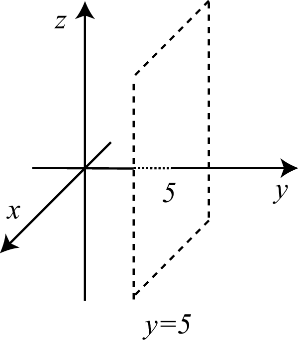
Fig. 5.5.1 The plane \(y=5\) defined in Listing 5.5.1.
   1:   [surface]
   2:     1   P      2 2 1  10
   3:     2   P      5 0 0  0 5 0  0 0 10
Arbitrary planes can be defined by specifying P as the symbol. In this case, two types of description can be used to define the plane: four parameters, \(A,B,C,D\), can be used to specify the plane equation \(Ax+By+Cz-D=0\); otherwise, the coordinates of three points, \((x_1,y_1,z_1),(x_2,y_2,z_2),(x_3,y_3,z_3)\), can be specified. The former method is useful when the normal vector \((s,t,u)\) and coordinates \((x_0,y_0,z_0)\) of one point on the plane are known. An equation of the plane satisfying these conditions would be given as
Then, because
the plane can be defined by setting \(A=s\), \(B=t\), \(C=u\), and \(D=sx_0+ty_0+uz_0\). The surface number 1 shown in this example is defined as a plane having the normal vector \((2,2,1)\) and containing the coordinate \((5,0,0)\). This surface corresponds to the plane denoted by the dashed line in Fig. 5.5.2. As an illustration of the latter method, surface number 2 is defined as a plane passing through the three coordinates \((5,0,0)\), \((0,5,0)\), and \((0,0,10)\). This surface coincides with surface 1 in Fig. 5.5.2.
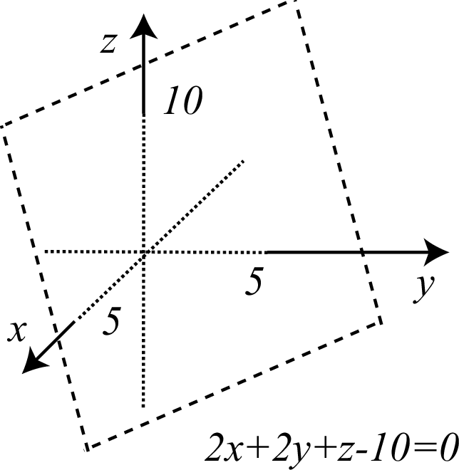
Fig. 5.5.2 The plane defined in Listing 5.5.2.
   1:   [surface]
   2:     1   SO     5
   3:     2   SZ     10  3
   4:     3   S      10 10 0  3
To define a sphere surface, the symbols SO, SX, SY, SZ, and S can be used. SO is used to define a sphere surface centered at the origin by specifying its radius \(R\) as a parameter. In the second line, a sphere surface centered at the origin with a radius of 5 cm is defined as surface number 1. The symbols SX, SY, and SZ can be used to define sphere surfaces centered on the \(x\), \(y\), and \(z\) axes, respectively. To use these symbols, two parameters, a coordinate value on the appropriate axis and the radius of the sphere, must be specified. In the third line, a sphere surface centered at the coordinate \((0,0,10)\), which is a point on the \(z\) axis, with a radius of 3 cm is defined as surface number 2. S can be used to define a sphere surface centered at an arbitrary coordinate \((x_0,y_0,z_0)\). In this case, four parameters, the coordinate values \(x_0,y_0,z_0\) and the radius \(R\), must be specified. In the fourth line, a sphere surface centered at the coordinate \((10,10,0)\) with a radius of 3 cm is defined as surface number 3. The three sphere surfaces defined in this example are shown in Fig. 5.5.3.
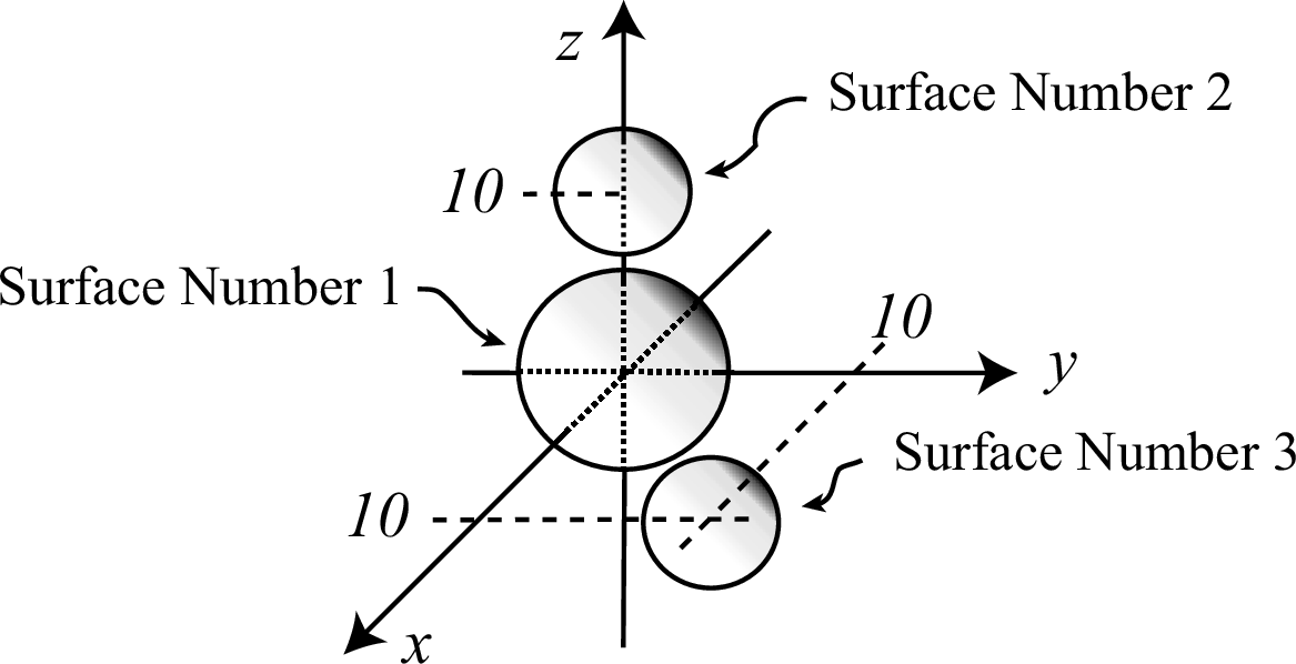
Fig. 5.5.3 The three sphere surfaces defined in Listing 5.5.3.
   1:   [surface]
   2:     1   CY     5
   3:     2   C/Y    15 0  3
To define a cylinder surface having a central axis along either the \(x\), \(y\), or \(z\) axes, the symbols CX, CY, and CZ, respectively, can be specified. In this case, the radius \(R\) must be specified as a parameter. In the second line, a cylinder surface with a central axis on the \(y\) axis with a radius of 5 cm is defined. This surface corresponds to the surface of the cylinder shown in the upper-right of Fig. 5.5.4. The symbols C/X, C/Y, and C/Z can be used to define a cylinder surface with a central axis parallel to the \(x\), \(y\), and \(z\) axes, respectively. In this case, two coordinate values and the radius of the cylinder must be specified. The third line defines a cylinder surface with a central axis parallel to the \(y\) axis. The coordinates \(x_0=15\) and \(z_0=0\) are specified as the first and second parameters, respectively, and the radius is given by the third parameter. This surface corresponds to the cylinder in the lower-left side of Fig. 5.5.4.
To define a cylinder surface with a central axis that is not parallel to any of the \(x\), \(y\), and \(z\) axes, the symbol GQ can be used. However, it is easier to use CX, CY, CZ, C/X, C/Y, and C/Z and then perform a coordinate transformation using the [transform] section than it is to use GQ.
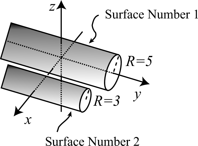
Fig. 5.5.4 The two cylinder surfaces defined in Listing 5.5.4.
   1:   [surface]
   2:     1   KZ     0  1
   3:     2   K/Z    0 20 0  1/3  1
A cone surface with a central axis along the \(x\), \(y\), and \(z\) axes can be defined by specifying the symbols KX, KY, and KZ, respectively. Parameters defining the coordinate of the vertex, an angle parameter \(|t|^2\), and a sheet parameter k (optional) must also be set. An example in which KZ is specified is shown in the second line. The first parameter is the \(z\) coordinate of the vertex of the cone, \(z_0=0\), and the second defines \(|t|^2=1\). The equation of KZ is
After substituting each of the parameters, the following equations are obtained:
This formulation corresponds to surface number 1, which is defined as the cone surface having a central axis on the \(z\) axis with its vertex at \((0,0,0)\). This surface is shown on the left side of Fig. 5.5.5. The cone in the region \(z>0\) is represented by the first equation, while that in \(z<0\) is given by the second equation; these surfaces are specified by k=1 and k=-1, respectively. Note that, as k is not specified in the second line of the example, both surfaces are defined. The parameter \(|t|^2\) is given by the relation \(|t|^2=\tan^2\theta\), where \(\theta\) is the angle between the central axis and the generating line. In the case of surface number 1, \(\tan\theta=1\), and therefore \(\theta=45^\circ\). To define a cone surface with a central axis parallel to either the \(x\), \(y\), or \(z\) axes and a vertex at \((x_0,y_0,z_0)\), the symbols K/X, K/Y, and K/Z, respectively, can be used. The third line shows an example in which K/Z is specified. The coordinate of the vertex is \((0,20,0)\), and the cone has a central axis parallel to the \(z\) axis. Its angle \(\theta\) is \(30^\circ\), corresponding to \(|t|^2=1/3\), or \(\tan\theta=1/\sqrt{3}\). In this case, only one cone surface in the region of \(z>0\) is defined by specifying k=1. Note that one-sheet cone (k=pm 1) should not have a skew transformation. If you want to rotate a one-sheet cone surface, specify another surface to cut a two-sheet cone instead of defining the k parameter.
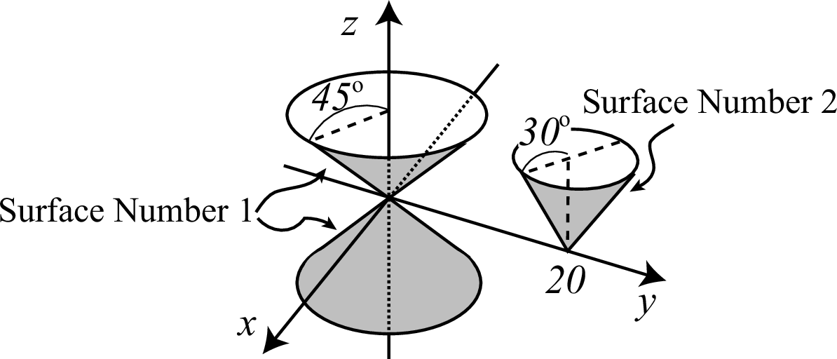
Fig. 5.5.5 The cone surface defined in Listing 5.5.5.
   1:   [surface]
   2:     1   SQ     1/9**2 1/6**2 1/3**2  0 0 0  -1  0 0 0
To define an ellipsoid surface as shown in Fig. 5.5.6, the symbol SQ is specified. The general equation of an ellipsoid surface is
where \(a\), \(b\), and \(c\) are the lengths of the semi-principal axes along the \(x\), \(y\), and \(z\) axes, respectively. An ellipsoid surface can therefore be defined by specifying the first to the seventh parameters of SQ as \(A=1/a^2\), \(B=1/b^2\), \(C=1/c^2\), \(D=E=F=0\), and \(G=-1\), respectively. In this example, an ellipsoid surface with lengths \(a=9\), \(b=6\), and \(c=3\) cm is defined. To define a spheroid surface, the two lengths along the two axes that are not the rotational axis must have same values. For example, if the \(x\) axis is the rotational axis, \(b\) must be set equal to \(c\), namely, \(B=C\). The eighth, ninth, and tenth parameters of SQ correspond to the coordinates of the center, \(x_0\), \(y_0\), and \(z_0\), respectively. In this example, the center of the ellipsoid is the origin \((0,0,0)\). Note that if \(D\), \(E\), and \(F\) are set to non-zero values, a quadric surface other than an ellipsoid is defined.
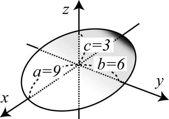
Fig. 5.5.6 The ellipsoid surface defined in Listing 5.5.6.
   1:   [surface]
   2:     1   SQ     1/6**2 1/3**2 -1/5**2  0 0 0  -1  0 0 0
   3:     2   SQ     -1/6**2 -1/3**2 1/5**2  0 0 0  -1  0 20 0
The symbol SQ can be specified to define hyperboloid surfaces, as shown in Fig. 5.5.7. The surface in the center of the figure is called the hyperboloid of one sheet; those on the right-hand side are hyperboloids of two sheets. Equations of hyperboloids of one and two sheets are given as, respectively,
Here, the central axis is the \(z\) axis. If \(a=b\), the shape is called a hyperboloid of revolution. Surface number 1 corresponds to the hyperboloid of one sheet. In the second line, the first to the seventh parameters of SQ are given as \(A=1/6^2\), \(B=1/3^2\), \(C=-1/5^2\), \(D=E=F=0\), and \(G=-1\), respectively. The central axis, which corresponds to the \(z\) axis, passes through the origin because the eighth to tenth parameters are set to \(x_0=0\), \(y_0=0\), and \(z_0=0\), respectively. The intersection of this hyperboloid with a plane vertical to the \(z\) axis is an ellipse. The left side of Fig. 5.5.7 shows the intersection line of surface number 1 with the plane \(z=0\). This ellipse has the major and minor radii of \(a=6\) cm and \(b=3\) cm, respectively. The surface defined in the third line corresponds to the hyperboloid of two sheets. In this case, the signs of \(a\), \(b\), and \(c\) are reversed, and \(D=E=F=0\) and \(G=-1\) are specified. Note that the central axis passes through the coordinate \((0,20,0)\) as \((x_0,y_0,z_0)=(0,20,0)\) is set in the eighth, ninth, and tenth parameters, respectively. When a surface of a hyperboloid of two sheets is used to define a cell in the [cell] section, one region of the coordinate system \((x_0,y_0,z_0)\) represents the negative sense, while the remaining space represents the positive sense. The interiors of the two sheets should be specified as positive.
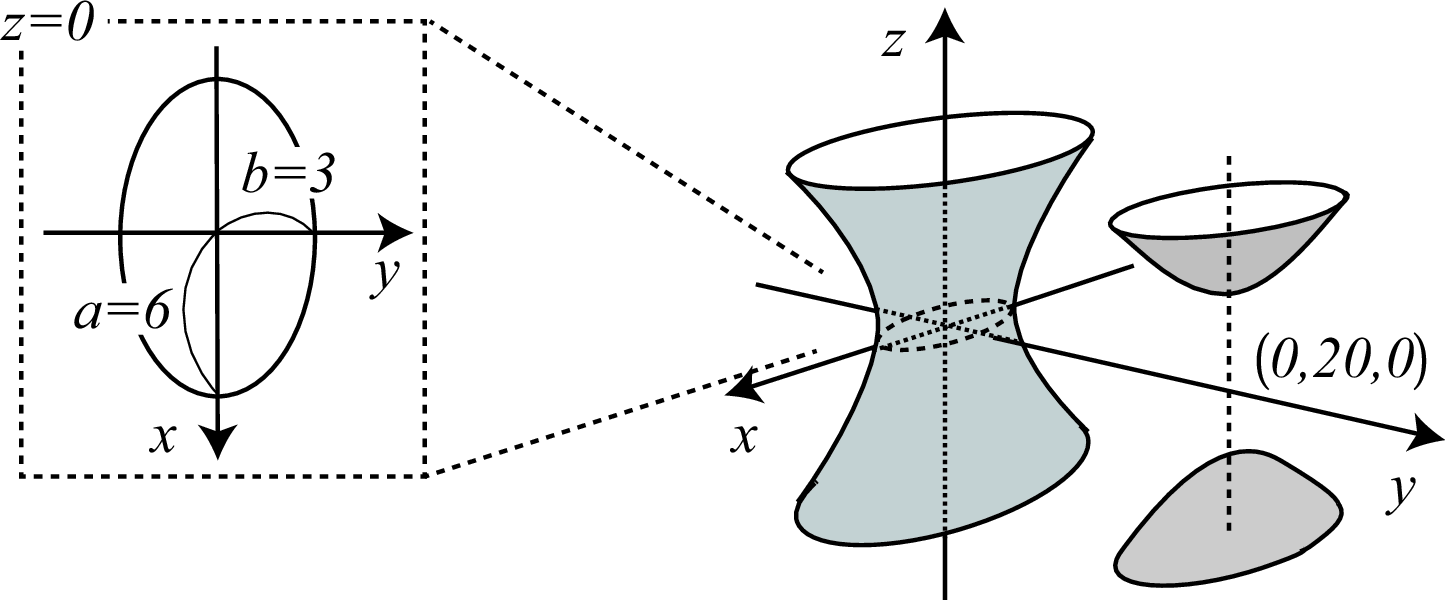
Fig. 5.5.7 The hyperboloid surface defined in Listing 5.5.7.
   1:   [surface]
   2:     1   SQ     1 1/2**2 0  0 0 -1  0  0 0 0
To define a paraboloid surface as shown in Fig. 5.5.8, the symbol SQ can be specified. The equation of a paraboloid surface with a central axis coinciding with the \(z\) axis is given as
This surface can be defined by specifying \(A=1/a^2\), \(B=1/b^2\), \(C=0\), \(D=E=0\), \(F=-1\), and \(G=0\) as the first to seventh parameters, respectively, of SQ. In the example, a paraboloid with \(a=1\) and \(b=2\) is defined. The intersection of this paraboloid with a plane including the \(z\) axis is a parabola. The intersection lines of the paraboloid with \(y=0\) and \(x=0\) are shown in the left and right panels of the figure, respectively. The coordinates of the vertex are specified by the eighth through tenth parameters; in this case, \(x_0=0\), \(y_0=0\), and \(z_0=0\).
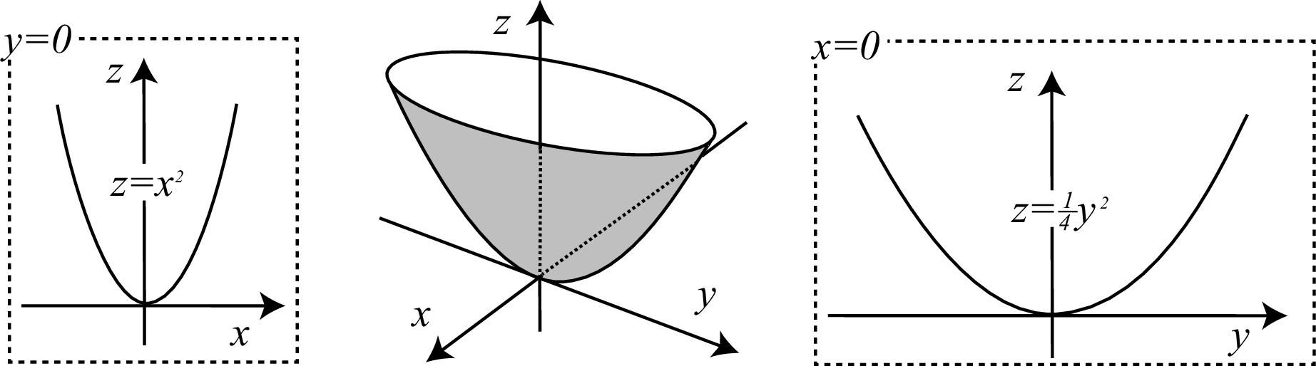
Fig. 5.5.8 The paraboloid surface defined in Listing 5.5.8.
   1:   [surface]
   2:   set: c1[30]
   3:   set: c2[cos(c1/180*pi)]
   4:   set: c3[sin(c1/180*pi)]
   5:     1   GQ     c2**2 1/2**2 c3**2  0 0 -2*c2*c3  -c3 0 -c2  0
Arbitrary surfaces expressed by quadratic equations in \(x\), \(y\), and \(z\) can be defined by specifying the symbol GQ. Although similar surfaces such as CX, KX, and SQ are also expressed by quadratic equations, GQ can be used to represent quadratic surfaces with a central axis that is not parallel to the \(x\), \(y\), and \(z\) axes. Note that it is easier to apply a coordinate transformation in the [transform] section to CX, KX, and SQ than it is to use GQ. This example represents a paraboloid surface obtained by rotating the surface in Listing 5.5.8 by an angle of \(30^\circ\) around the \(y\) axis. The result is shown in Fig. 5.5.9. The parameters of this example were obtained by calculating the following transform defined by rotating the coordinate \((x,y,z)\) by an angle of \(\theta\) around the \(y\) axis:
This relation gives
After substitution of this result into the paraboloid equation, the following equation of \(x'\), \(y'\), and \(z'\) is obtained:
Comparing this result with the equation of GQ in Table 5.5.2 and specifying the corresponding parameters defines a paraboloid surface rotated by an angle \(\theta\) around the \(y\) axis. In this example, \(\theta=30^\circ\) is given as the constant c1, while c2 and c3 are defined as \(\cos\theta\) and \(\sin\theta\), respectively.
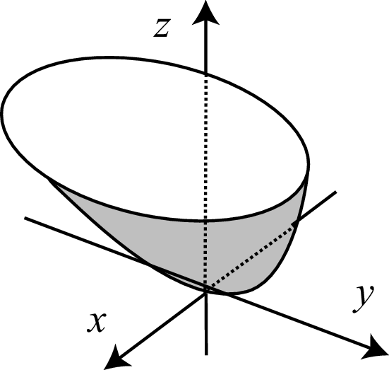
Fig. 5.5.9 The paraboloid surface defined in Listing 5.5.9.
   1:   [surface]
   2:     1   TZ     0 0 0  10 3 5
A torus surface can be obtained by rotating an ellipse around a rotational axis outside of the ellipse. In PHITS, torus surfaces with rotational axes corresponding to the \(x\), \(y\), and \(z\) axes can be specified using the symbols TX, TY, and TZ, respectively. The equation of a torus surface with the \(z\) axis as the rotational axis is given as
In this case, the ellipse has major and minor radii \(a\) and \(b\), respectively, and the distance between the center of the ellipse and the rotational axis is given by \(R\). The center of the torus surface in this example is set at the origin by setting the first, second, and third parameters of TZ to zero. The fourth, fifth, and sixth parameters are \(A=R=10\) cm, \(B=b=3\) cm, and \(C=a=5\) cm, respectively. The intersection line of the torus with the plane \(z=0\) is shown in the left panel of the figure. The distance between the \(z\) axis and the center of the ellipse is 10 cm and the width of the ring is \(5\times2=10\) cm. The intersection of the torus with the plane \(y=0\) is shown in the right panel of the figure; note that only the region \(x>0\) is shown. The major and minor radii of the ellipse are 5 and 3 cm, respectively.
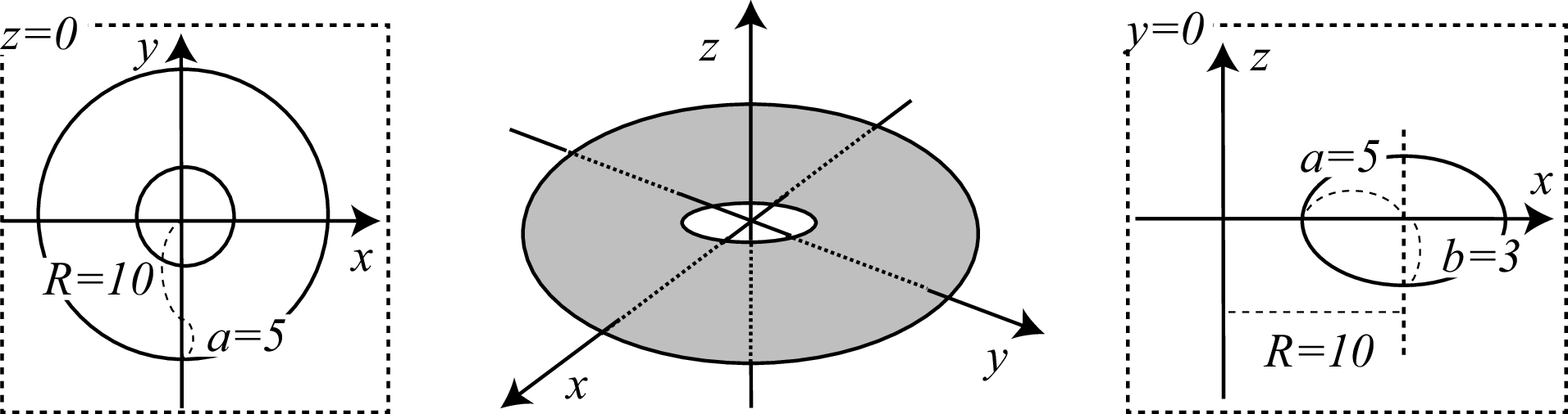
Fig. 5.5.10 The torus surface defined in Listing 5.5.10.
   1:   [surface]
   2:     1   BOX    5 5 0  9 0 0  0 6 0  0 0 3
The symbol BOX can be specified to define the surfaces of an arbitrary rectangular solid. As parameters of BOX, the coordinates of the base point \(P(x_0,y_0,z_0)\) and each component of three vectors \(\mathbf{A}(A_x,A_y,A_z)\), \(\mathbf{B}(B_x,B_y,B_z)\), and \(\mathbf{C}(C_x,C_y,C_z)\) must be defined. The figure shows the relation between the base point and the three vectors. In this example, the coordinate of the base point is \((5,5,0)\) and the three vectors are given as \(\mathbf{A}=(9,0,0)\), \(\mathbf{B}=(0,6,0)\), and \(\mathbf{C}=(0,0,3)\). When using BOX, vectors \(\mathbf{A}\), \(\mathbf{B}\), and \(\mathbf{C}\) do not have to be parallel to the \(x\), \(y\), and \(z\) axes, but they should be vertical to each other.
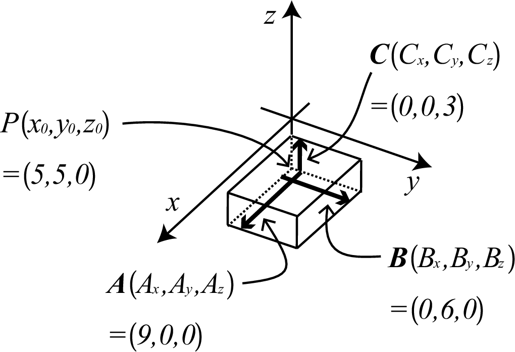
Fig. 5.5.11 The rectangular surface defined in Listing 5.5.11.
   1:   [surface]
   2:     1   RPP    5 14  5 11  0 3
To define the surfaces of a rectangular solid surrounded by three sets of two planes parallel to the \(xy\), \(yz\), and \(zx\) planes, the symbol RPP can be used. Unlike BOX, an arbitrary rectangular solid with surfaces not parallel to the \(x\), \(y\), and \(z\) axes cannot be defined. The six parameters of RPP must be set by the user as the maximum and minimum values in the \(x\), \(y\), and \(z\) coordinate system. In this example, \(x_{\min}=5\), \(x_{\max}=14\), \(y_{\min}=5\), \(y_{\max}=11\), \(z_{\min}=0\), and \(z_{\max}=3\) are specified as the six parameters. The result is the same rectangular solid defined in Listing 5.5.11.
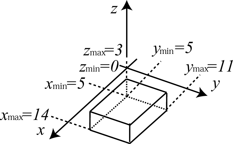
Fig. 5.5.12 The rectangular surface defined in Listing 5.5.12.
   1:   [surface]
   2:     1   SPH    5 5 5  5
The symbol SPH can be used to define a sphere surface with an arbitrary coordinate as its center. The first, second, and third parameters are components of the coordinate \((x_0,y_0,z_0)\), and the fourth parameter is the radius of the sphere. A sphere surface centered at \((5,5,5)\) with a radius of 5 cm is defined in this example. There is no functional difference between the symbols SPH and S.
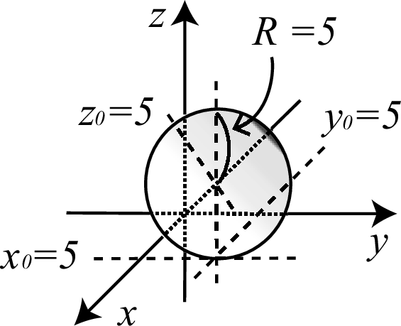
Fig. 5.5.13 The sphere surface defined in Listing 5.5.13.
   1:   [surface]
   2:     1   RCC    5 5 0  0 0 10  5
The symbol RCC can be used to define an arbitrary cylinder surface. The parameters of RCC are the coordinates of the center of the bottom of the cylinder, \(P(x_0,y_0,z_0)\), a vector from the bottom to the top, \(\mathbf{H}(H_x,H_y,H_z)\), and the radius of the cylinder, \(R\). The relation between these parameters is shown in the figure. In this example, the coordinate \(P(5,5,0)\) is the center of the bottom circle, the vector is \(\mathbf{H}=(0,0,10)\), and the radius is 5 cm. Unlike symbols such as CX and C/X, it is useful to define a cylinder surface with a central axis not parallel to the \(x\), \(y\), and \(z\) axes.
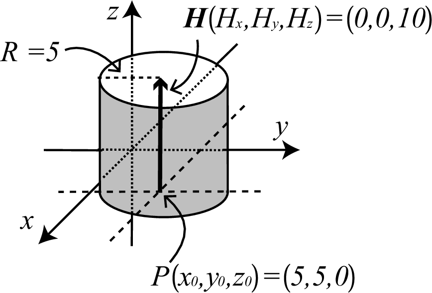
Fig. 5.5.14 The cylinder surface defined in Listing 5.5.14.
   1:   [surface]
   2:     1   RHP    0 0 0  0 0 10  5 0 0  2 -5 0  -2 -5 0
The symbols RHP or HEX can be used to define hexagonal prism surfaces. As parameters, the center coordinate of the bottom of the prism, \(P(x_0,y_0,z_0)\), a vector from the bottom to the top, \(\mathbf{H}(H_x,H_y,H_z)\), and three vectors, \(\mathbf{A}(A_x,A_y,A_z)\), \(\mathbf{B}(B_x,B_y,B_z)\), and \(\mathbf{C}(C_x,C_y,C_z)\), must be specified. Vectors \(\mathbf{A}\), \(\mathbf{B}\), and \(\mathbf{C}\) are required to define the hexagon comprising the bottom and top surfaces. The left panel of the figure shows the relation between point \(P\) and the three vectors; namely, the lengths and directions of the perpendicular lines between \(P\) and the three contiguous sides of the hexagon determine the three vectors. In this example, the origin is at the center of the bottom hexagon and the height along the \(z\) axis of the prism is 10 cm. The components of the origin \((0,0,0)\) are specified as the first, second, and third parameters of RHP, respectively, and those of the vector \(\mathbf{H}=(0,0,10)\) are given as the fourth, fifth, and sixth parameters, respectively. The seventh to fifteenth parameters are the \(x\), \(y\), and \(z\) components of \(\mathbf{A}\), \(\mathbf{B}\), and \(\mathbf{C}\), respectively. The defined hexagon shown in the figure is symmetric with respect to the \(y\) axis.
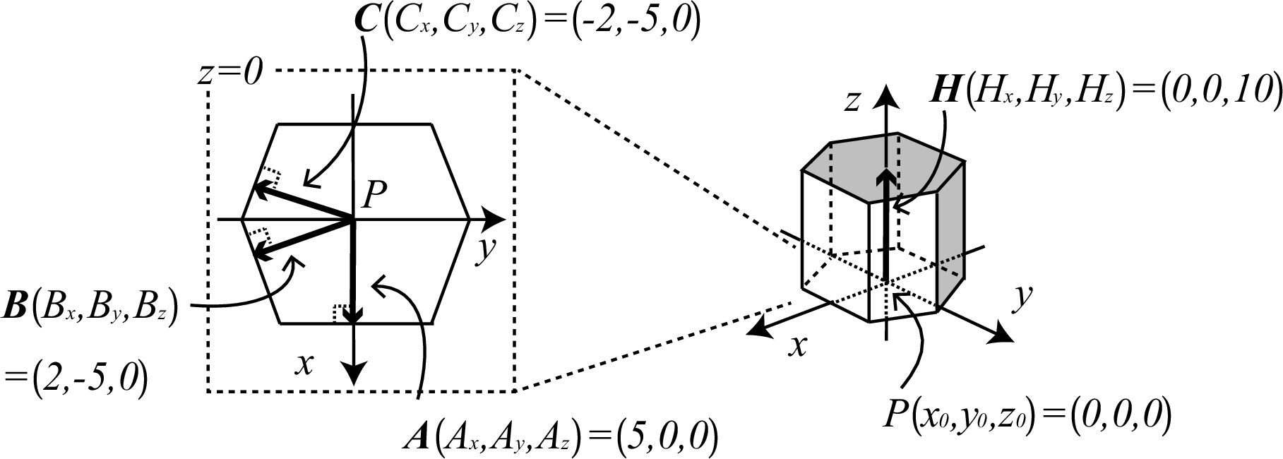
Fig. 5.5.15 The hexagonal prism surface defined in Listing 5.5.15.
   1:   [surface]
   2:     1   REC    0 0 0  0 0 10  5 0 0  0 2 0
The symbol REC defines elliptical cylinder surfaces. The parameters of REC are the coordinates of the center coordinate of the bottom surface, \(P(x_0,y_0,z_0)\), the components of a vector from the bottom to the top, \(\mathbf{H}(H_x,H_y,H_z)\), and the components of two vectors, \(\mathbf{A}(A_x,A_y,A_z)\) and \(\mathbf{B}(B_x,B_y,B_z)\). The relation between the point \(P\) and the two vectors \(\mathbf{A}\) and \(\mathbf{B}\) is shown in the figure. The major and minor axis vectors \(\mathbf{A}\) and \(\mathbf{B}\) must both be defined using initial point \(P\), which is the center of the ellipse. The surfaces of an elliptical cylinder with a height along the \(z\) axis of 10 cm are defined in this example. The center of the bottom is the origin; the first, second, and third parameters of REC are the coordinates of the origin \((0,0,0)\), and the fourth, fifth, and sixth parameters are those of vector \(\mathbf{H}=(0,0,10)\). The \(x\), \(y\), and \(z\) components of \(\mathbf{A}\) and \(\mathbf{B}\) are given in the seventh to twelfth parameters. The vectors \(\mathbf{A}\) and \(\mathbf{B}\) are used to form the ellipse shown in the figure.
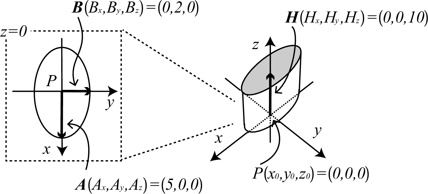
Fig. 5.5.16 The elliptical cylinder surface defined in Listing 5.5.16.
   1:   [surface]
   2:     1   TRC    0 0 0  0 0 10  5  2
The surfaces of a truncated right-angle cone can be defined by specifying the symbol TRC. As parameters of TRC, each component of the center coordinate \(P(x_0,y_0,z_0)\) of the cone bottom, the components of a vector from the bottom to the top, \(\mathbf{H}(H_x,H_y,H_z)\), and two radii of the bottom and top circles, \(R_1\) and \(R_2\), must be specified. In this example, the surfaces of the truncated right-angle cone of height 10 cm along the \(z\) axis are defined. The center of the bottom circle is the origin. The coordinates of the origin \((0,0,0)\) are specified as the first, second, and third parameters, respectively, and those of vector \(\mathbf{H}=(0,0,10)\) are given as the fourth through sixth parameters. The radius of the bottom is \(R_1=5\) cm and that of the top is \(R_2=2\) cm with \(R_1\) and \(R_2\) specified as the seventh and eighth parameters, respectively.
\(R_2\) cannot be set to zero when defining TRC. To set a typical cone, that is, a non-truncated cone, using TRC, \(R_2\) should be set to a small value.
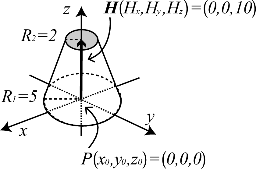
Fig. 5.5.17 The cut cone surface defined in Listing 5.5.17.
   1:   [surface]
   2:     1   ELL    3 3 0  -3 -3 0  9
The surface of an ellipsoid of revolution, a spheroid, can be set by defining the symbol ELL. After defining an ellipse by specifying the coordinates of two focal points or the coordinate of its center, the ellipsoid of revolution is defined by rotating the ellipse around its major axis. Note that the meanings of the first six parameters of ELL depend on the sign of the seventh parameter, \(R\). This example is an example with \(R>0\). In this case, the coordinates of the two focal points and the radius of the major axis must be specified. The coordinate of the first focus, \(P_1(x_1,y_1,z_1)\), is given by the first, second, and third parameters, while that of the second, \(P_2(x_2,y_2,z_2)\), is given by the fourth, fifth, and sixth parameters. The seventh parameter is the radius of the major axis, \(R\). The first and second focal points are \(P_1=(3,3,0)\) and \(P_2=(-3,-3,0)\), respectively. The ellipse is on the \(xy\) plane, with an angle between the major axis and the \(x\) axis of \(45^\circ\). The length of the major axis is \(2R=18\) cm. The ellipsoid is defined by rotating this ellipse around the major axis.
Although an ellipsoid surface can also be defined using SQ, it is easier to define an ellipsoid with an inclined rotational axis using ELL. Note that only surfaces of ellipsoids of revolution can be defined using ELL.
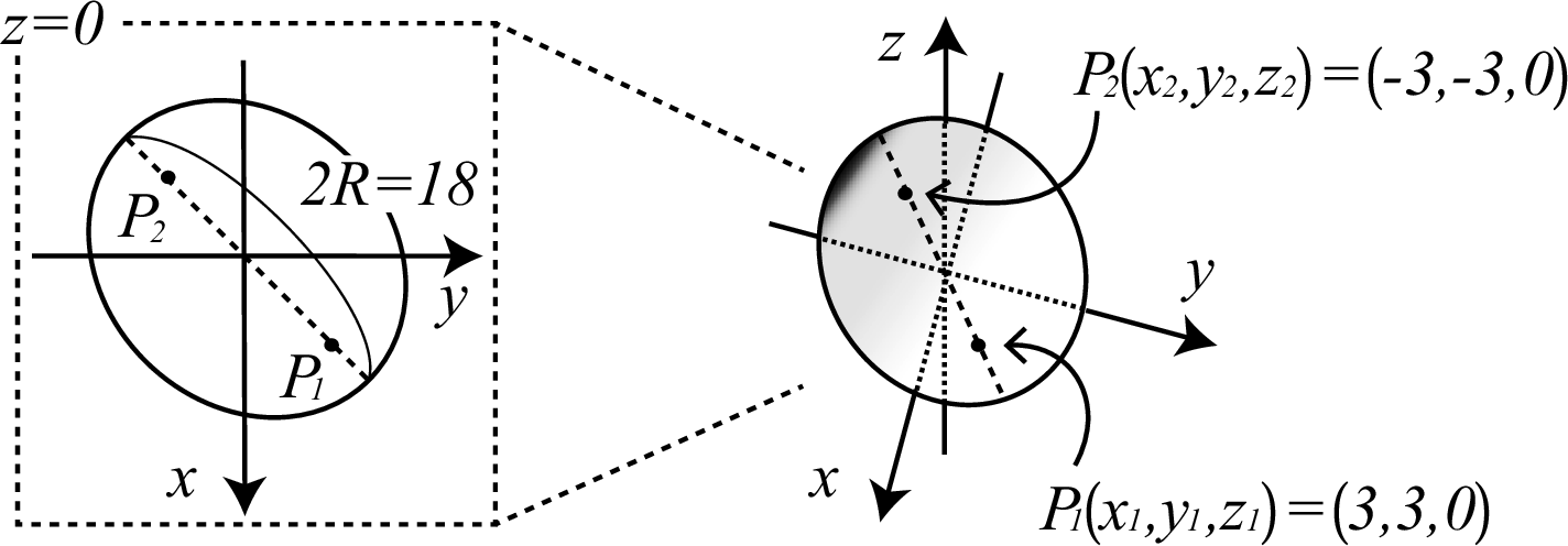
Fig. 5.5.18 The spheroid surface defined in Listing 5.5.18.
   1:   [surface]
   2:     1   ELL    0 0 0  6 6 0  -6
This example applies to the case \(R<0\) in ELL. In this case, the center coordinate \(P\), major axis \(\mathbf{A}\), and radius of the minor axis of the ellipse must be defined. In this example, the center of the ellipse corresponds to the origin. The first, second, and third parameters of ELL are given as \(P(x_0,y_0,z_0)=(0,0,0)\), while the fourth, fifth, and sixth parameters are \(\mathbf{A}(A_x,A_y,A_z)=(6,6,0)\). The ellipse defined by these parameters is shown in the figure. The absolute value of the seventh parameter, \(R\), which corresponds to the radius of the minor axis, is 6 cm. The ellipsoid surface obtained by rotating this ellipse around the major axis is also shown in the figure.
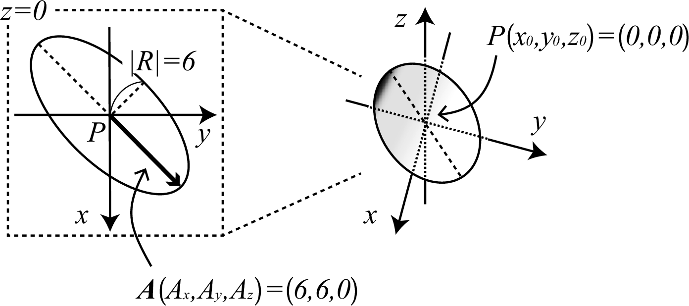
Fig. 5.5.19 The spheroid surface defined in Listing 5.5.19.
   1:   [surface]
   2:     1   WED    0 0 0  10 0 0  0 10 0  0 0 5
A wedge surface can be obtained by specifying the symbol WED. Note that only a right triangle can be used as the bottom of a wedge defined by WED. In this example, one vertex of the bottom triangle \(P(x_0,y_0,z_0)=(0,0,0)\) is given in the first, second, and third parameters of WED, respectively. Two vectors \(\mathbf{A}(A_x,A_y,A_z)=(10,0,0)\) and \(\mathbf{B}(B_x,B_y,B_z)=(0,10,0)\) with initial point \(P\) are specified in the fourth to ninth parameters. The triangle defined by the two vectors is a right triangle. The height vector of the wedge, \(\mathbf{H}(H_x,H_y,H_z)=(0,0,5)\), is given in the tenth through twelfth parameters.
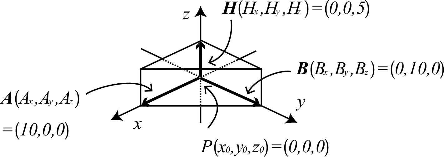
Fig. 5.5.20 The wedge surface defined in Listing 5.5.20.
5.5.3. Surface definition by macro body
In using a surface defined by a macro body in the cell definition, - refers to the inside of the macro body and + is the outside. Each surface comprising a macro body can be used in the cell definition, in which case the macro body surface number should be written as . plus the macro body surface number.
The surface numbers are listed in Table 5.5.4.
Symbol |
Macro body surface number |
Explanation |
|---|---|---|
BOX |
1 |
Surface vertical with the end of \((A_x, A_y, A_z)\). |
BOX |
2 |
Surface vertical with the origin of \((A_x, A_y, A_z)\). |
BOX |
3 |
Surface vertical with the end of \((B_x, B_y, B_z)\). |
BOX |
4 |
Surface vertical with the origin of \((B_x, B_y, B_z)\). |
BOX |
5 |
Surface vertical with the end of \((C_x, C_y, C_z)\). |
BOX |
6 |
Surface vertical with the origin of \((C_x, C_y, C_z)\). |
RPP |
1 |
Surface at \(x_{\max}\). |
RPP |
2 |
Surface at \(x_{\min}\). |
RPP |
3 |
Surface at \(y_{\max}\). |
RPP |
4 |
Surface at \(y_{\min}\). |
RPP |
5 |
Surface at \(z_{\max}\). |
RPP |
6 |
Surface at \(z_{\min}\). |
SPH |
Only a user-defined surface number is used. |
|
RCC |
1 |
Side face of cylinder. |
RCC |
2 |
Surface vertical with the end of \((H_x, H_y, H_z)\). |
RCC |
3 |
Surface vertical with the origin of \((H_x, H_y, H_z)\). |
RHP / HEX |
1 |
Surface vertical with the end of \((A_x, A_y, A_z)\). |
RHP / HEX |
2 |
Opposite face for surface 1. |
RHP / HEX |
3 |
Surface vertical with the end of \((B_x, B_y, B_z)\). |
RHP / HEX |
4 |
Opposite face for surface 3. |
RHP / HEX |
5 |
Surface vertical with the end of \((C_x, C_y, C_z)\). |
RHP / HEX |
6 |
Opposite face for surface 5. |
RHP / HEX |
7 |
Surface vertical with the end of \((H_x, H_y, H_z)\). |
RHP / HEX |
8 |
Surface vertical with the origin of \((H_x, H_y, H_z)\). |
REC |
1 |
Side face of cylinder. |
REC |
2 |
Surface vertical with the end of \((H_x, H_y, H_z)\). |
REC |
3 |
Surface vertical with the origin of \((H_x, H_y, H_z)\). |
TRC |
1 |
Side face of cone. |
TRC |
2 |
Surface vertical with the end of \((H_x, H_y, H_z)\). |
TRC |
3 |
Surface vertical with the origin of \((H_x, H_y, H_z)\). |
ELL |
Only a user-defined surface number is used. |
|
WED |
1 |
Surface including the top and bottom hypotenuses. |
WED |
2 |
Surface including \(\mathbf{B}\) and \(\mathbf{H}\). |
WED |
3 |
Surface including \(\mathbf{A}\) and \(\mathbf{H}\). |
WED |
4 |
Surface including \(\mathbf{A}\), \(\mathbf{B}\), and the end of \(\mathbf{H}\). |
WED |
5 |
Surface including \(\mathbf{A}\), \(\mathbf{B}\), and the origin of \(\mathbf{H}\). |